How to properly use the "Thin Lens Formula"
to model a 35mm camera 'thick' lens
(Revision 8.A - September 6, 2012; created 8/22/12)
This paper describes how to properly use the thin lens formula to
model a 35mm camera 'thick' lens, even at minimum focus distances
-- and how to accurately measure and determine the location of all
cardinal points in the model for a real 35mm lens.
The first half of this paper attempts to provide background information. The second
half jumps right into presenting and using the new thin lens formula
to model a Nikon 28-300 lens.
While the math at first may seem intimidating, nothing more than basic high school
math is needed to understand this paper.
The  thin lens formula,
1/f = 1/v + 1/b (see diagram below),
is often used to
model how a 35mm camera lens works. But what is rarely understood is
how to properly measure 'v' and 'b' for a thick lens. Almost always, the measurements
are large enough that errors caused by misuse of the formula are negligible and
not even noticed. However, when working with minimum focus distances, the errors
are significant. thin lens formula,
1/f = 1/v + 1/b (see diagram below),
is often used to
model how a 35mm camera lens works. But what is rarely understood is
how to properly measure 'v' and 'b' for a thick lens. Almost always, the measurements
are large enough that errors caused by misuse of the formula are negligible and
not even noticed. However, when working with minimum focus distances, the errors
are significant.
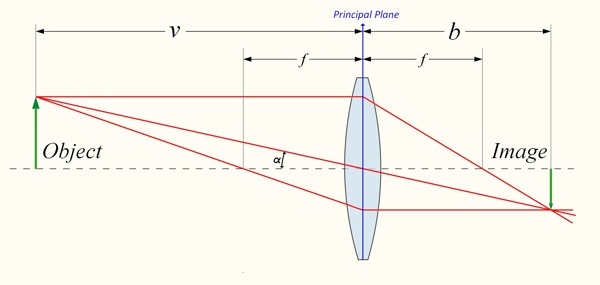
The "Thin Lens Formula": 1/f = 1/v + 1/b, resulting in a
half-angle of view of α
|
|
2. Background Information
|
|
Interactive demo: First, understand the thin lens model. Play around with the
following interactive demo (tips below; requires Java): start/reset demo
Java applets are now blocked in all web browsers. However, you can still run this interactive
demo (if your computer has Java installed) by running this command (from a command prompt):
java sun.applet.AppletViewer https://www.panohelp.com/thinlensformula.html
After running: (1) click on 'Lens' button, then click in the center of the window, and
(2) click on 'Object', and then click anywhere to the left of the lens.
TIPS for understanding the interactive demo:
- The left arrow represents a real-world object. Lines represent rays of
light emanating from a single point on an object, being 'focused'
by a lens. Where all three rays intersect on the right is the only
'in focus' point.
- Click on the top of the left arrow, and once highlighted, slowly drag the
arrow down. Notice where the 'in focus' point is (it traces out the arrow).
So the right arrow represents the 'in focus' image of the object (where the film
plane must be to record an 'in focus' photo).
- Pretend that the right edge of the interactive window is the film plane. To
take in 'in-focus' photo, the inverted arrow must align there. Do so
by moving the lens. Next, move the object closer to the lens. Now, 'focus'
by changing the focal length of the lens (also known as 'focus breathing').
- Notice that the 'angle of view' of the lens is determined not by the lens
focal length (click on the lens to drag focal points), but rather by
the 'focusing distance', b. The reason this is so confusing is that at infinity
focus (where all lens manufactures provide specifications for their lenses),
b is equal to f.
- Add a 'beam' to mimic an object at infinite distance. Change the angle of
the beam and notice the plane of 'in focus' points is the focal point plane.
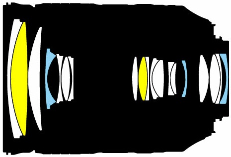
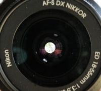
AF-S NIKKOR 28-300mm f/3.5-5.6G ED VR
|
35mm lenses are thick: But most 35mm camera lenses are a compound lens with
non-trivial length and are then by definition a thick lens system ("A lens of non-negligible
thickness"). Additionally, many modern lenses contain
aspherical lens
elements and are asymmetrical.
As an example, consider a Nikon lens (seen right)
with 19 lens elements in 14 lens groups.
So why is the thin lens model used?: The thin lens model is often used to describe
a 35mm lens at infinity focus, where some terms and known
inaccuracies (like not accounting for lens asymmetry) go to zero. For example, at infinity focus,
v is ∞, so the term 1/v is 1/∞, which equals zero,
meaning that the thin lens formula simply states that b is equal to f,
the focal length of the lens.
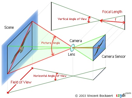
Focal Length confusion: The digital photography website
www.dpreview.com
defines "focal length" in terms of focus at infinity and a distance from the "optical
center of the lens". But then the dpreview diagram (seen right) does not match their definition.
The diagram shows a finite focus distance, with the
effective focal length (defined below) incorrectly labeled as the "focal length".
In other words, dpreview has labeled the 'b' distance in the thin lens
equations as the focal length.
Tamron also defines focal length
as the 'b' distance in the thin lens formula (and not the 'f' distance), adding to the confusion.
What is 'focal length' anyway? The internet is full of formulas
for converting between 'angle of view' and 'focal length', but what
most don't disclose is that these calculations are only 'valid' for a
hypothetical lens that is focused at infinity.
For example, take a hypothetical 35mm camera lens, with only a single thin lens
with a fixed focal length of 50mm. If you want to focus on objects
at 'infinity', then the distance to the in-focus image on the film plane,
b, becomes (b=1/(1/50-1/∞)), or 50mm, with
a diagonal angle of view of 46.8° (on a full frame 35mm sensor).
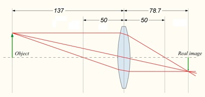
But if you take the same fixed 50mm lens and want to focus
it on a very close object, say at 137mm from the lens (b=137; seen right),
then the distance to the in-focus image (the film plane), b becomes 78.7mm
(b=1/(1/50-1/137)), with a diagonal angle of view of 30.7°.
In other words, to focus the image of a close subject on the
film plane, the lens needed to be moved 28.7mm further away from the film
plane, which reduces the angle of view recorded by the photo by a third.
Effective focal length: Let's just define "effective focal length" to mean:
The focal length of a lens focused at infinity that provides the same picture angle.
Therefore, in the example above, the focal length of the lens is 50 mm, but the
effective focal length is 78.7 mm.
To avoid confusion, this 'effective focal length' definition is NOT the
combined 'front focal length' and the 'back focal length' seen elsewhere
in discussions about thick lenses.
The reason we don't define effective focal length as the 'b' distance
will become clear below, once lens asymmetry is taken into account.
Nikon uses 'effective focal length', but calls it "Focusing Length":
Review Nikon's
Lens Simulator.
Conspicuously absent is the term "focal length". Instead, Nikon uses "Focusing Length", but
what does that mean? The "angle of view" Nikon provides for a "focusing length"
precisely matches the angle of view for a lens focused at infinity
(for a focus distance of only a couple hundred feet).
Therefore, Nikon is using 'effective focal length', but their name for it is "Focusing Length".
|
Internal Focusing:
In the example above, when we wanted to focus at an object 137mm away from the
lens. Rather than pushing the 50mm lens 28.7mm further away, what happens when
we keep the lens at 50mm away from the film plane, but replaced it with a 36.6mm
(1/(1/137+1/50)) lens? The angle of view in the photo remains the same
at 46.8 , and we have just focused on a much closer object.
Check out Nikon's
28-300 lens manual,
which states "This lens is equipped with the
Internal Focusing
(IF) system. As
the shooting distance decreases, the focal length also decreases." Now
you know part of the reason for that (altering focal length to achieve focus).
|
Distances when modeling a true thin lens: From the thin lens diagram at the
top of this page, it is clearly seen, but rarely understood, that the 'v' and 'b'
distances are measured from a principal plane. And in a thin lens model, there
is a single principal plane, which just happens to align with the center of
the lens. Because of this, the distance from the object
to the film plane just happens to equal v+b.
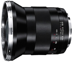
Carl Zeiss Distagon 21mm
|
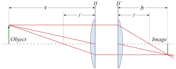
Distances when modeling a thick lens: The thin lens formula may be used to model
a thick lens system, but with one huge caveat that most people miss.
There are two hypothetical principal planes (H and H';
not in the same location) in a thick lens system and
distances v and b must be measured from the proper
principal plane
Source and principal plane definition.
More Information.
As a result, the distance from the object to the film plane will not equal v+b.
|
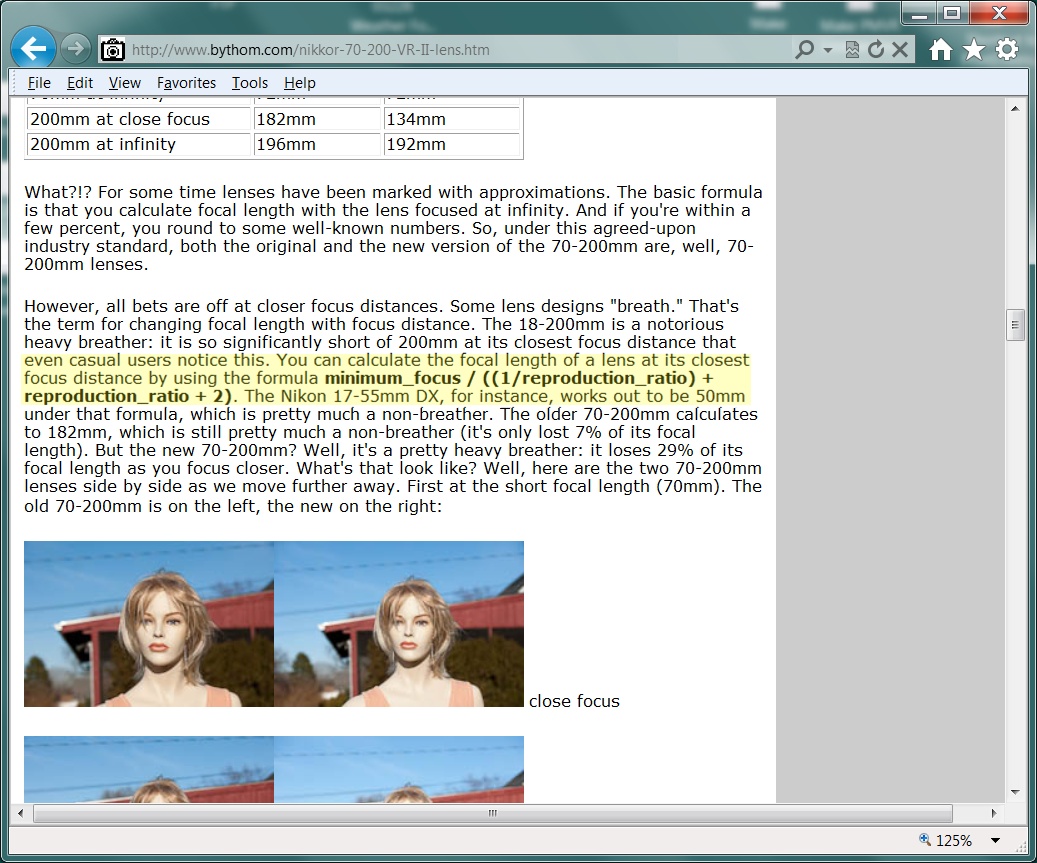
Even photography experts misunderstand this concept. Thom Hogan
presented a formula
(view;
archived)
for determining a DSLR lens focal length at minimum focus distance,
that IS just the thin lens formula
rewritten -- incorrectly assuming that v+b was equal
to the minimum focus distance.
|
Principal Plane Defined: A hypothetical plane in a lens system in which all
light refraction can be considered to happen. Namely, in the diagram at the top
of this page, we could show the refraction of the light as the light
enters and exits the lens, but we don't. Instead, we show light refracted at
the principal plane. The end result is the same (light ends up at the same place)
except that now we have a simplified model of the lens to work with.
Planes in the Thin Lens Model: There is a single principal plane in a thin
lens model. Notice in the interactive demo above, light rays hit the blue vertical
line (the principal plane), and then refract -- even though actual refraction takes
place twice on the lens surfaces.
Planes in the Thick Lens Model: There are two principal planes in a thick lens
model (think of the thin lens model pulled apart; seen right), where all light rays can be considered
to refract (even though the actual refraction is far more complex).
How to draw construction rays
in a thick lens system.
|
Warning: The principal planes in both a thin lens and thick lens are hypothetical
planes. Light does not actually refract there. Drawing rays that refract at the principal planes
accurately models the end result of where the light ray terminates, but it does not
show the actual path that light takes through the lens system.
|
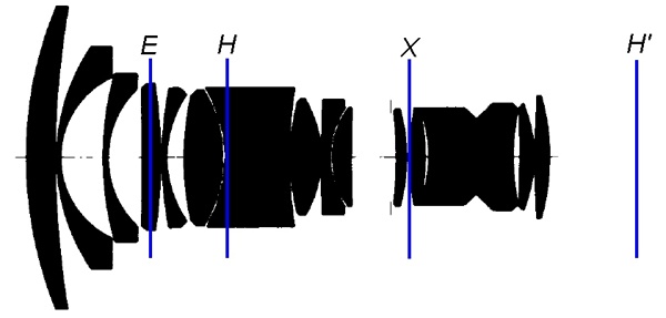
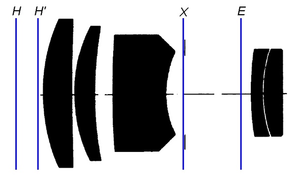
Thick Lens Example:
For example, here is the internal lens layout for the Carl Zeiss Distagon 21mm
lens (photo above right), with the H and H' principal planes,
entrance pupil 'E', and exit pupil 'X' marked as per the
lens specification.
Notice that the H and H' principal planes are 75.5mm apart.
Carl Zeiss Distagon 21mm
|
The thin lens formula can be used to model this lens, but only if the v distance
is measured from H and the b distance is measured from H'.
|
An exercise for the reader: Using the lens specification, figure out why H' is where it
is. Hint: infinity focus
|
WARNINGS: (1) The location of the principal planes for a lens
are not necessarily at a fixed location, but rather, can change location depending upon
focus distance, etc. (2) The principal planes are used to model a lens and do not
provide any information about how light rays actually refract in a lens system.
Carl Zeiss Sonnar 135mm
|
Therefore, unless you know a lot of information about
a particular lens, even finding the location of H and H' is
not immediately obvious (but not that hard either; see below).
If your goal was to find the angle of view (and the effective focal
length) for your lens, doing so by direct measurement is far easier
than finding the locations of principal planes.
Modern lens design is non-intuitive: Seen right is a Carl Zeiss Sonnar 135mm,
where the entire lens is under 133mm from the film plane. But far more interesting
is that the entrance pupil 'E' is closer to the film plane than the exit pupil, and that
both object and image principal planes are in front of the lens.
Lens Specification.
|
Once again: The planes do not reflect the path actual light takes
through a lens. Rather, they provide a model of where the in-focus
image on the film plane should be.
|
| Nikon 18-55 @18 F3.5 |
Entrance Pupil
| |

Exit Pupil
|
Lens Asymmetry: When a lens is symmetrical, the entrance pupil
coincides with the H principal plane and the exit pupil coincides with the H'
principal plane.
But when the diameter of the exit pupil has a different diameter than
the diameter of the entrance pupil (example right for the same F3.5), then
a lens is asymmetrical, and the principal planes are displaced.
Accounting for lens asymmetry: Lens asymmetry affects the thin lens
formula, and angle of view (effective focal length) calculations.
For details, refer to two excellent
photographic optics
papers by Paul van Walree on the subject:
|
3. The new thin lens model
|
|
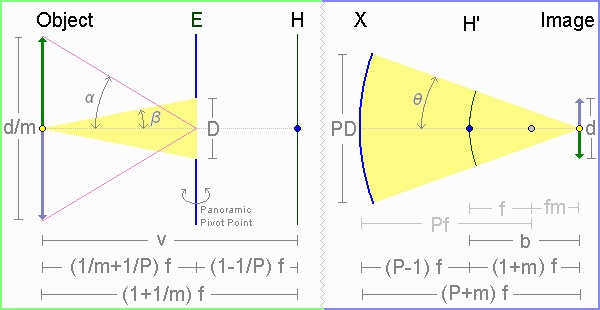
Here is the new thin lens model, that accounts for lens asymmetry and close focus distances
(Relative distances between planes are not to scale; rather, planes have been placed
for readability of formulas. Diagram drawn for P>1; If P<1, formulas still work, but order
of planes changes):
Where:
f = lens focal length¹
H = object principal plane
H' = image principal plane
v = object distance (from H)
b = image distance (from H')
d = film (image sensor) dimension
m = reproduction ratio (image size/object size)
E = entrance pupil (panoramic pivot point how to measure)
X = exit pupil
D = entrance pupil diameter
P = Pupil magnification (rear/front)
α = half-angle of photo field of view
β = half-angle of light cone in object space
θ = half-angle of light cone in image space
F = effective focal length
N = effective F-number
|
Useful formulas and relationships:
f = 1/(1/v + 1/b)
m = b/v = tan(β)/tan(θ)
f = X/(P+m) = E/(1/m+1/P)
F = f×(1+m/P) = X/P = E×m = D×N
X = P×F
N = (f/D)×(1+m/P) = F/D = 1/(2×sin(θ)) = X/PD
D = F/N
α = atan(d/(2×F))
tan(β) = tan(θ)×m
|
¹A 'real' thick lens usually has a different 'front focal length' than
a 'back focal length', combined into what some call an 'effective focal length'. But
since we already use 'effective focal length' for something else, we just use
'lens focal length'.
|
4. How to derive the new thin lens model
|
|
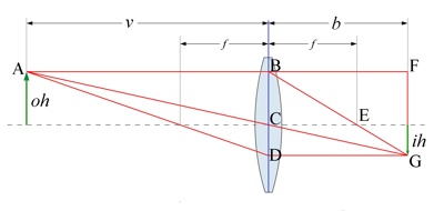
1/f = 1/v + 1/b: tan(∠BEC)=tan(∠BGD), or oh/f=(oh+ih)/b. Rewrite as b/f = (oh+ih)/oh.
tan(∠BAC)=tan(∠FAG), or oh/v = (oh+ih)/(b+v). Rewrite as (oh+ih)/oh = (b+v)/v. Therefore b/f=
(b+v)/v. Divide both sides by b to get 1/f = (b+v)/(b×v). Simplify to 1/f = 1/v + 1/b.
With the thin lens formula proven assign the image (film plane) as dimension d. The object is
size d/m (where m is an unknown scaling factor). Note that the triangle formed by the
'object' to H is similar to the triangle formed by the 'image' to H'.
m=b/v: Separate the principal planes in the thin lens model to emphasize that they are not
the same point in a thick lens. By the thin lens geometry (similar triangles), divide all sides
of the image space triangle by m. We now have equal triangles, so b/m = v. Rewrite as m = b/v.
b=(1+m)×f: Rewrite m=b/v as as v=b/m and place into the thin lens formula
1/f = 1/(b/m) + 1/b. Solve for b to find that b = (1+m)×f.
v=(1+1/m)×f: Rewrite m=b/v as b=m×v and place into the thin lens formula
1/f = 1/v + 1/(m×v). Solve for v to find that v=(1+1/m)×f.
N=1/(2×sin(θ)): See
numerical aperture
and
Optics in Photography (page 107).
This is the key formula for deriving the remaining formulas, and the reason why we draw the
yellow-tinted image cone in the diagram.
This simple equation hides an important concept about light intensity -- that it
is inversely proportional (to the square of) the distance from the light source.
Inverse-square law.
The implication: As the distance from the in-focus image to the exit pupil changes (the 'fm' distance
seen right caused by non-infinity focus), to maintain the same aperture value (and focal length), the
size of the exit pupil must change accordingly. Conclusion:
Pupil size must change as focus distance changes (to maintain a fixed aperture)!
f/N=D: This is just the numerical aperture formula rewritten, that only applies at infinity focus (m=0)
and a symmetrical (P=1) lens,
that tells us we should label the entrance pupil dimension as D.
But what is rarely understood is that f is not one edge of a triangle, but rather is the
radius of a portion of a sphere. See page 107 of
Optics in Photography
by Rudolf Kingslake.
Namely, the image 'planes' are not planes at all, but for any well-corrected lens,
is actually a portion of a sphere.
PD: Define P to be some unknown scaling factor that yields the exit pupil dimension,
from the entrance pupil dimension. In other words, P is: 'exit pupil dimension / entrance pupil dimension'.
X-H'=(P-1)×f:
At infinity focus, you get a radius b=f and a side D at H' (by numerical aperture formula).
Multiply all sides by P. You now have a radius P×f with a side PD. Therefore, with the distance from
f to H' known to be f, and the distance from f to X known to be P×f, subtract to obtain the distance from
X to H' to get P×f-f or (P-1)×f.
X=(P+m)×f:
Now consider non-infinity focus situation and realize that the difference between
b and f is (1+m)×f-f or f×m. So the distance from X to the image is just the sum of the
distance from X to f (found to be P×f in prior step) to f×m to get P×f+m×f, or
(P+m)×f. Also, find by adding b distance to X-H' distance.
E-H=(1-1/P)×f: The thin lens formula tells us how distances in image space
are related to distances in object space (from respective principal planes). Therefore,
with the distance from X to H' known to be negative (P-1)×f, set that to 'b' in the thin
lens formula to solve for the corresponding 'v' distance in object space (the distance
from E to H). So, 1/f = 1/v - 1/((P-1)×f) and solving for v yields
(1-1/P)×f, the distance from E to H.
E=(1/m+1/P)×f:
With v known, and the distance from E to H known, find the E distance as
E = (1+1/m)×f - (1-1/P)×f, or (1/m+1/P)×f.
F=f×(1+m/P): The tangent of the angle α is half of d/m divided
by the E distance. Therefore, α = atan(((d/m)/2)/((1/m+1/P)×f)).
Multiply by m/m and realize the familiar atan(d/(2×f) formula, but scaled by
(1+m/P). Therefore, define F as f×(1+m/P).
D=F/N: Using the numerical aperture formula, we find in image space that PD = X/N. Divide
both by sides by P. X/P is F, so D = F/N.
Also confirmed by computing in object space:
D = 2×tan×(β)×(1/m+1/P)×f = 2×tan(θ)×m×(1/m+1/P)×f
= 1/N×(1+m/P)×f = F/N
|
5. Validating the formulas
|
|
Testing the formulas with an actual lens: It is important to test and verify
that the formulas actually work. Actual test data will be used (we don't use Nikon
published 'tech specs', which are sometimes notoriously wrong).
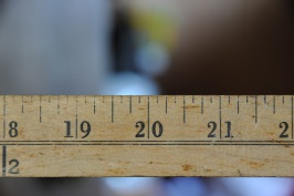
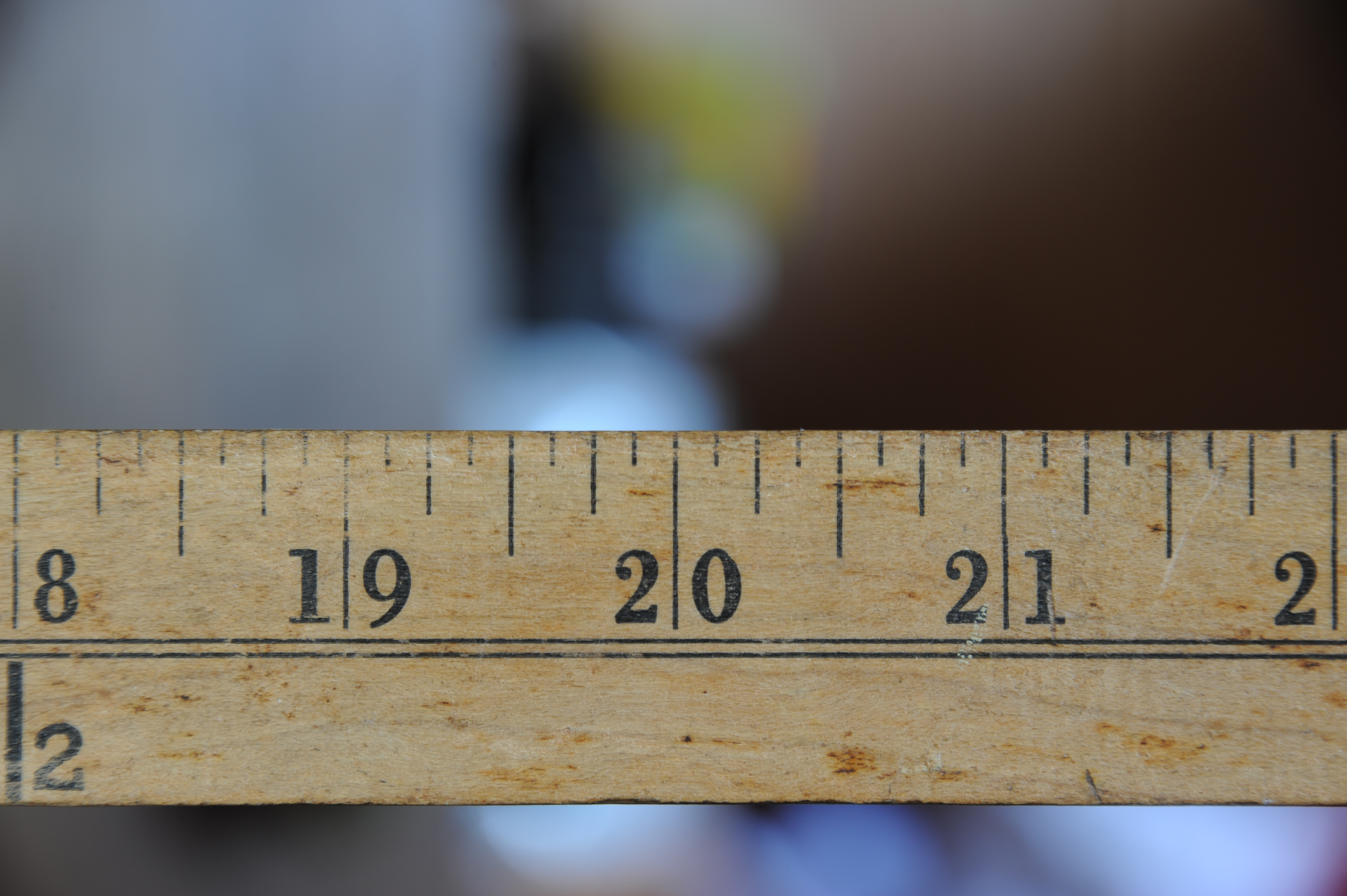
A Nikon D700 FX body was used with a Nikon 28-300
FX lens. The lens was set to maximum focal length (300mm). Since prior testing
indicated a minimum focus distance slightly under 18", the film plane mark on the D700
was placed at exactly 18" from a ruler. Focus was fine-tuned with live view, and then
focus was set to manual (to lock on that focus distance). A
photo
was taken, showing 4.0805" (4×4256/4172) on the ruler, a
reproduction ratio of m=0.34734 (36/4.0805/25.4).
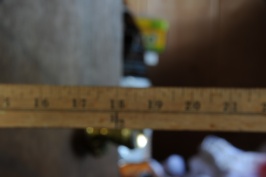
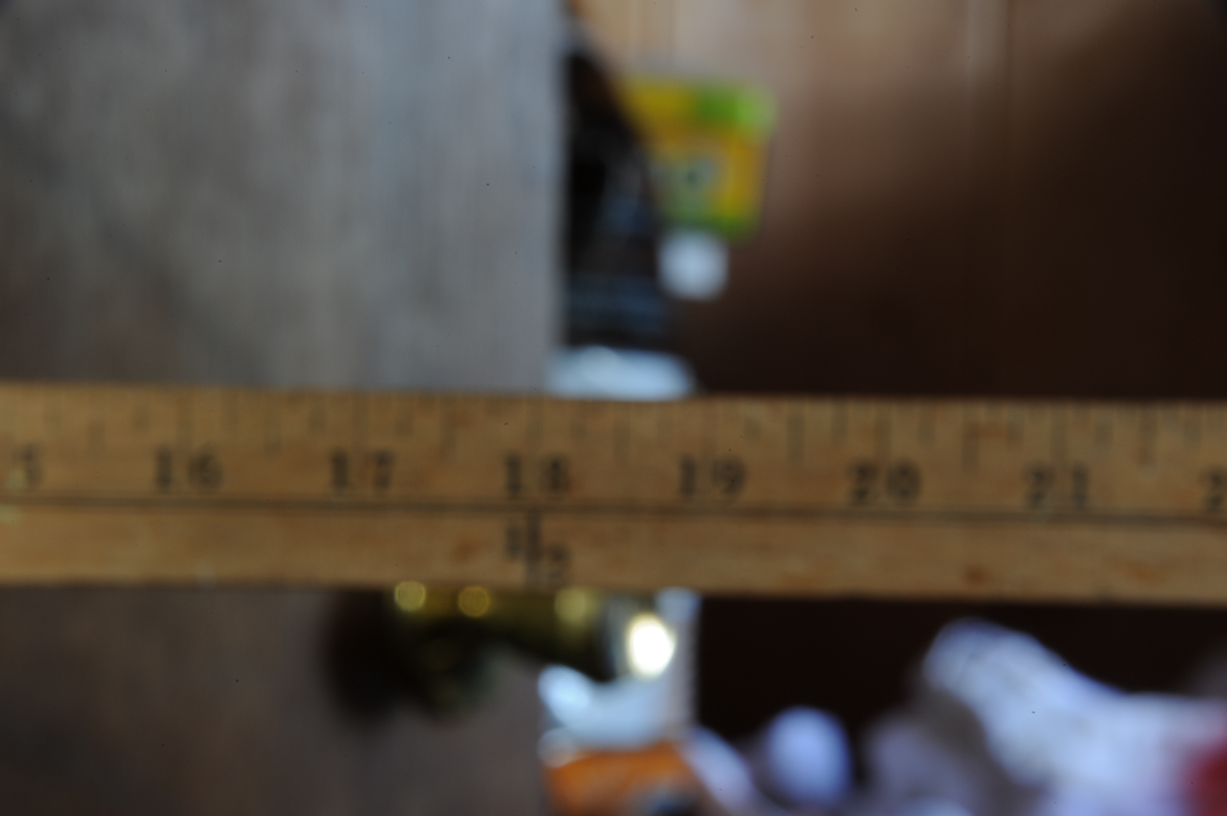
The film plane was moved back to 30" from the ruler and another
photo
taken (focus still at 18"), showing 7.0162" (5×4256/3033) on a ruler.
Plugging these numbers (and from the prior test) into a
FOV and entrance pupil calculator
yielded: angle of view = 13.95°; effective focal length = 147.13;
entrance pupil 1.325" in front of film plane.
To validate the results, the film plane was moved back to 284.5" and a
photo was taken outside (focus still at 18").
The photo showed a width of 69.36" (60.375×4256/3706; with 60.375 the distance
between the center of the green vertical bars). Plugging these numbers into the
same FOV test as above along with the first photo numbers yielded: angle of
view = 13.97°; effective focal length = 146.97; entrance pupil 1.344" in
front of film plane.
With the numbers validated (to within error tolerances), use an effective focal
length that is the average of the two tests F=147.05 ((147.13+146.97)/2),
and by F=E×m, compute E=423.36 (147.05/.34734).
|
Testing a misused Thin Lens formula: Let's intentionally misuse the thin lens formula
(seen all the time in forums) and see what results we get when we assume that 'v' and
'b' are measured from the same principal plane:
v + b = 18" = 457.2mm
m = b/v = .34734, which is v = b/.34734
b/.34734 + b = 457.2
b = 457.2 / (1/.34734+1) = 117.86 = 118 mm
v = 457.2 - 117.86 = 339.34 mm
f = 1 / (1/v+1/b) = 1/(1/117.86+1/339.34) = 87.48 = 87 mm
And you get the same result by using
Thom Hogan's formula
(stated to work at the minimum focus distance):
f = 457.2 / (1/.34734 + .34734 + 2) = 87.48 = 87 mm
But by direct measurement, we know that the effective focal length should be 147,
not 118. This is the type of 'significant' error you get by assuming a single
pricipal plane in a thick lens system.
Testing the new thin lens formula assuming lens symmetry: It is left as an
exercise for the reader to calculate the results obtained by not accounting for
lens asymmetry. Do so by using P=1, and knowing E and m, calculate f in Object
space. Then using P=1, and knowing X and m, calculate f in Image space. You
end up with a contradiction that tells you P=1 is incorrect.
Testing the new thin lens formula: Let's properly account for both measurements
from the principal planes and for lens asymmetry. The
original photo contains EXIF information
(online EXIF viewer)
indicating the location of the exit pupil, at 120.5mm. Also, by direct measurement, P appeared
to be (9/16)/(11/16) or 9/11. This is now enough information to calculate f (internal
lens focal length), and F (the effective focal length):
m = .34734
P = 9/11
X = 120.5
f = X/(P+m) = 120.5/(9/11+.34734) = 103.39
F = X/P = 120.5/(9/11) = 147.28 = 147 - correct!
E = F/m = 147.28/.34734 = 424.02
The result shows that the new thin lens formula is
accurately modeling the Nikon 28-300 lens.
However, since it is incredibly difficult
to accurately measure 'P' (as a
small distance divided by another small distance is prone to error) we have
enough direct measurements to actually calculate what 'P' should have been:
F = X/P
P = X/F = 120.5/147.05 = 0.81945
In summary:
A thick lens can be accurately modeled by the new thin lens
formula by following these steps:
- Take two very carefully measured photos as per this
FOV and entrance pupil calculator,
which allows you to calculate 'm', 'E', and 'F'.
m = .34734
E = 423.36
F = 147.05
- EXIF data provides you an 'X', which allows 'P' to be calculated. Or, without EXIF data, measure 'P' and calculate 'X'.
X = 120.5
P = X/F = 120.5/147.05 = 0.81945
- Calculate f, b,H' and v,H.
f = X/(P+m) = 120.5/(.81945+.34734) = 103.27
b = H' = (m+1)×f = (.34734+1)×103.27 = 139.15
v = H = (1+1/m)×f = (1+1/.34734)×103.27 = 400.61
- Validate the calculations:
f = 1 / (1/v + 1/b) = 1 / (1/400.61 + 1/139.15) = 103
F = f×(1+m/P) = 103.27 × (1+.34734/0.81945) = 147
This allows a scale model of the camera, lens, and ruler to be constructed:
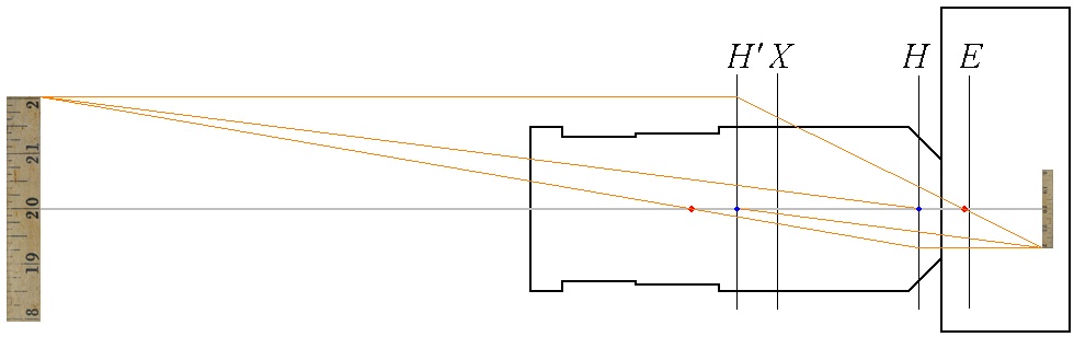
Scale model of Nikon 28-300 lens; 300mm; min focus distance; cardinal points/planes drawn;
An interesting side note: It is interesting to note what happens when we push
the ruler and 'H' plane away from the film plane by a distance of 82.55mm -- so that
the two principal planes H and H' align into a single principal plane --
and then 'misuse' the thin lens formula:
v + b = 18" + 82.55mm = 539.75mm
b/v = .34734, which is v = b/.34734
b/.34734 + b = 539.75
b = 539.75 / (1/.34734+1) = 139.15 mm
v = 539.75 - 139.15 = 400.6 mm
f = 1 / (1/v+1/b) = 1 / (1/400.6 + 1/139.15) = 103.28
In conclusion: The thin lens formula is often misused. But it can be
used to accurately model a thick lens when the principal planes, and lens
asymmetry, are properly accounted for.
|


